
Product Showcase

PRODUCT NAME
Hydraulic Oil Cylinder
The hydraulic oil cylinder supports comprehensive customization from specifications to functional scenarios, offering selection design and localized service support.
PRODUCT NAME
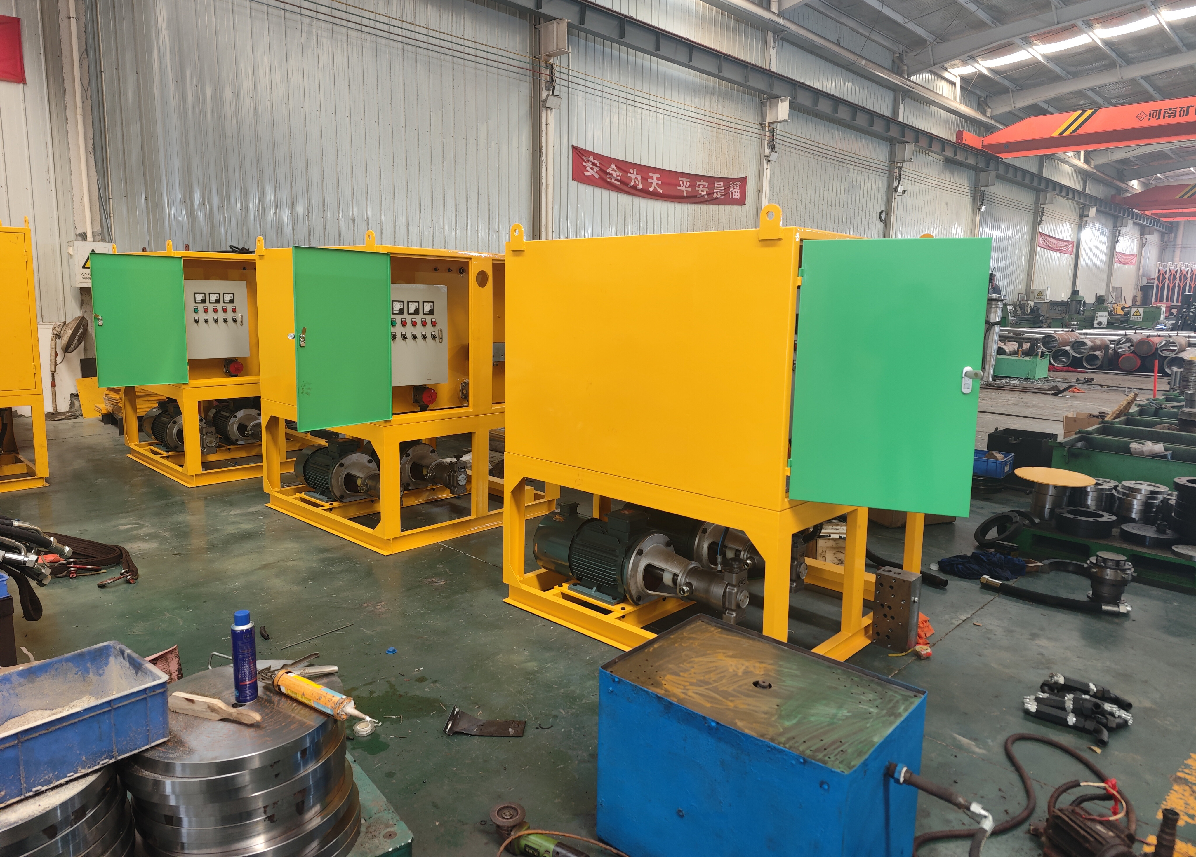
Hydraulic Pump Station
The hydraulic pump station supports full customization from specification parameters to functional scenarios, providing dedicated power solutions for equipment to achieve efficient and stable operation.

PRODUCT NAME
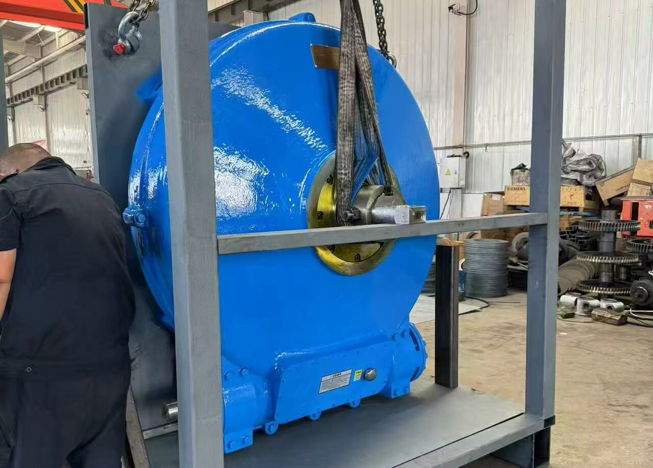
Dredger Reducer
Dredger reducers support non-standard customization covering JWZ series models, suitable for chemical, mining, and sewage treatment scenarios. Adjustable materials, dimensions, and performance parameters meet special working condition requirements.
PRODUCT NAME
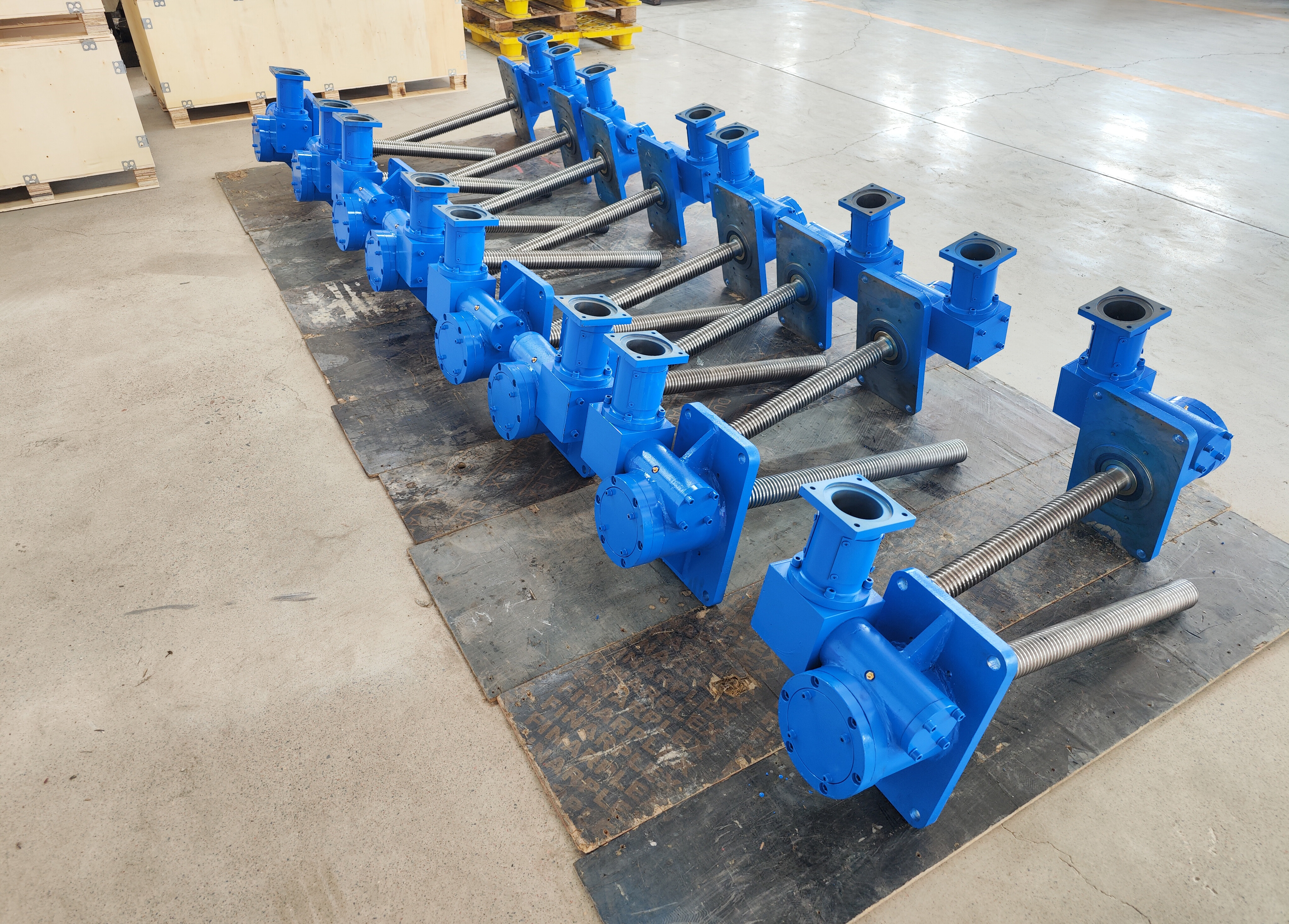
Screw Jack
The screw jack supports non-standard customization of load capacity, structure, material, and functionality to meet personalized transmission needs.
PRODUCT NAME
Worm Gear Reducer
The worm gear reducer's customization capability enables flexible adaptation to diverse industry needs, enhancing overall equipment performance and applicability.

PRODUCT NAME
Bevel Gear Rotary Divider
Designed for diverse industrial scenarios, including special installation forms and load-bearing requirements for mechanical equipment. Modular structure design facilitates component replacement, reducing maintenance costs and downtime.
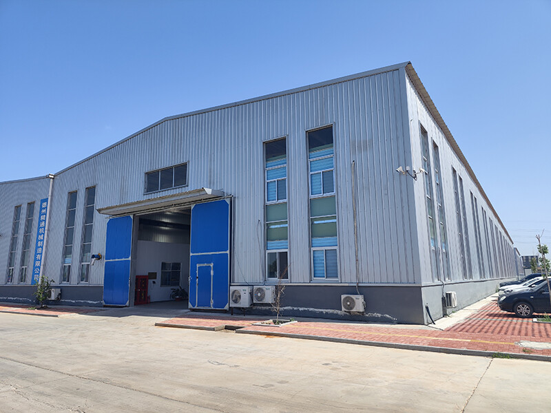
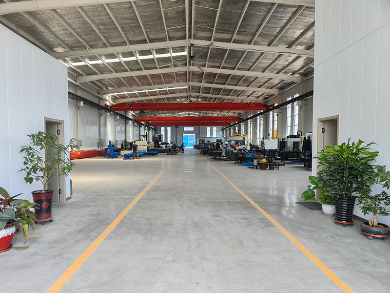
Dezhou Jingtong Machinery Manufacturing Co., Ltd.
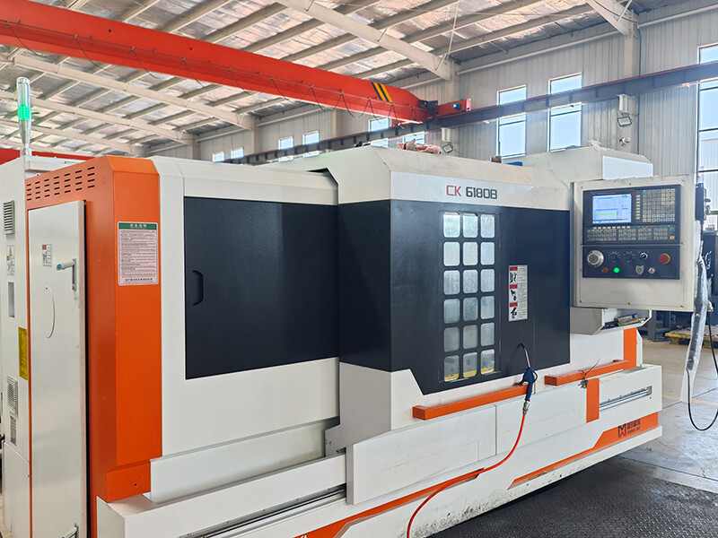
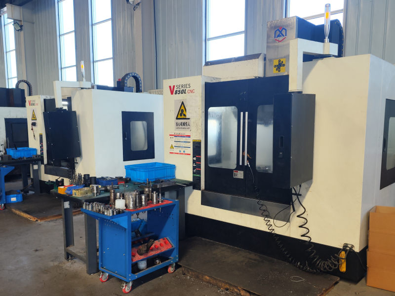
Dezhou Jingtong Machinery Manufacturing Co., Ltd. specializes in R&D and production of worm gear reducers, screw jacks, worm screw jacks, ball screw jacks, spiral screw jacks, planar double enveloping reducers, soft/hard-faced gear reducers, and customized non-standard reducer solutions for import localization. We also process non-ferrous metal castings and serve as a Shandong non-ferrous metal casting base. Equipped with complete R&D, production, sales, and technical service capabilities, we possess advanced processing centers. Our products feature exquisite craftsmanship, backed by strong technical expertise, advanced processes, and comprehensive testing. With complete specifications, competitive pricing, contract compliance, and after-sales support, we undertake special reducer design/manufacturing and provide innovative transmission solutions for modernization.
We uphold integrity, credibility, and century-enterprise principles, prioritizing customers through effective cooperation. In today's competitive market, success hinges not just on price but technical support, after-sales service, and strict quality control. Jingtong Machinery will continuously improve management, training, product development, sales, and after-sales service, maintaining our ethos of integrity, dedication, and innovation to establish new quality benchmarks and become an industry leader.
We serve clients with premium products, attentive service, and supreme credibility!
Certifications & Honors
 Enterprise Credit Rating Certificate
- Enterprise Credit Rating Certificate
- Quality service, integrity enterprise
- Contractual Credit Enterprises
- Honest Operation Demonstration Enterprise
- High-quality and trustworthy enterprises
- Respect credibility and serve enterprises
- Honest entrepreneur
- Honest Manager
- Civilized and Honest Unit
 Corporate credit evaluation AAA credit enterprise
 Quality system certification
 Bidding and Tendering Field Carbon Neutral Commitment Demonstration Unit


 worm-gear reducer
 worm-gear reducer
 CW series modular arc circular cylinder worm gear reducer
- Non-standard non-magnetic worm gear speed reducer
- SWL screw lift
- Central drive scraper decelerator
- Bevel Gear Direction Changer
- SJ spiral screw rod lifting machine
- JW Series Screw Lift
- Non-standard speed reducer
- Custom Worm Gears
- WH Series Arc Gear Cylinder Helical Rod Reducer
- Rotary support mud machine speed reducer
- Rotary support mud machine speed reducer
- Mixer scraper
- Electric lifting scraper reducer


Application Cases
 worm-gear reducerDirect shipping of Russian products, actual investment and use by Bega Ajour Mining Group
 worm-gear reducerDirect shipment of products to Russia, BAMC Group actually puts them into use
 S series gear reducerApplied in glass transmission equipment as the main drive application
 SWL screw liftAdjusting the up and down positions on the glass transmission device
- NMRV reducerApplication in light industrial transmission equipment
 cw worm gear worm gear reducerapplied in heavy industry synchronous transmission equipment
- JWZ scraper speed reducerUsed as the main drive in the sedimentation tank of the sewage treatment plant


