Overview
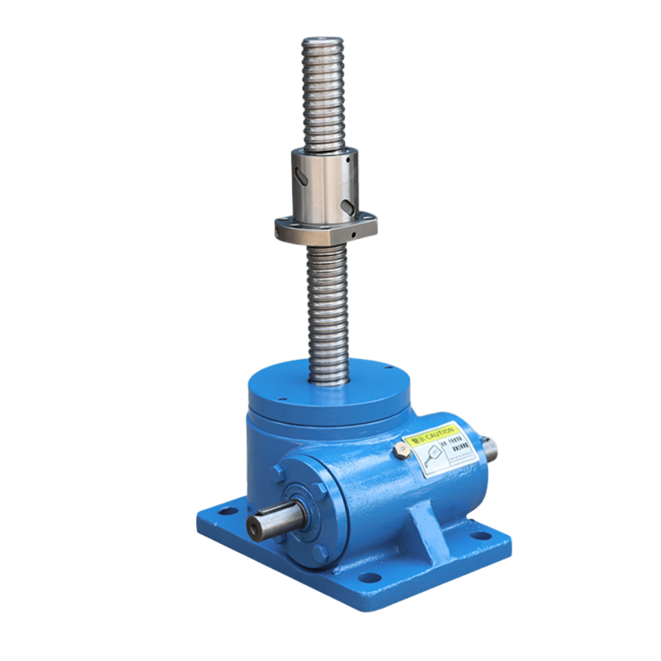
The SWL series worm gear screw jacks feature numerous functions, including lifting, lowering, propulsion with the aid of accessories, tilting, and various height adjustments. They are listed in the JB/T8809-1998 standard and are widely used in various industries such as machinery, metallurgy, construction, water conservancy, chemical industry, medical, and sports.
The SWL worm gear screw jack is a basic lifting component with many advantages, including compact structure, small size, light weight, no noise, safety and convenience, flexible use, high reliability, wide range of power sources, multiple supporting functions, and long service life. It can be used individually or in combination, and can accurately control and adjust the lifting or pushing height according to a specific program. It can be directly driven by an electric motor or other power source, or manually. Load capacity ranges from 2.5t to 120t, with a maximum input speed of 1500 rpm and a maximum lifting speed of 2.7m/min.
To improve the efficiency and load-bearing capacity of the SWL series worm gear screw jacks, special and advanced processes have been developed to enhance the overall performance of the jacks and meet the requirements of our customers.
SWL comes in different structural and assembly types, and the lifting height can be customized according to user requirements.
Type I structural form
model | SWL2.5 QWL2.5 | SWL5 QWL5 | SWL10/15 QWL10/15 | SWL20 QWL20 | SWL25 QWL25 |
SWL35 |
SWL50 |
SWL100 |
SWL120 |
S | Itinerary +20 | Itinerary +20 | Itinerary +20 | Itinerary +20 | Itinerary +20 | Itinerary + 2 0 | Itinerary +20 | Itinerary +20 | Itinerary +20 |
S, | Itinerary +110 | Itinerary +110 | Itinerary +110 | Itinerary +190 | Itinerary +205 | Itinerary +205 | Itinerary +285 | Trip +350 | Trip +400 |
S | 150.5 | 193 | 230 | 262 | 317 | 350 | 416 | 550 | 570 |
A | 165 | 212 | 235 | 295 | 350 | 430 | 475 | 527 | 526 |
B | 120 | 155 | 200 | 215 | 260 | 280 | 500 | 526 | 622 |
M | 135 | 168 | 190 | 240 | 280 | 360 | 385 | 622 | 412 |
N | 90 | 114 | 155 | 160 | 190 | 210 | 406 | 412 | 508 |
H | 97 | 130 | 150 | 176 | 217 | 240 | 280 | 360 | 360 |
h | 45 | 61.5 | 70 | 87 | 102 | 115 | 121 | 155 | 155 |
h | 12 | 14 | 16 | 20 | 25 | 30 | 32 | 38 | 42 |
d(k₆) | 16 | 20 | 25 | 28 | 34 | 38 | 38 | 45 | 48 |
d | 14 | 17 | 21 | 28 | 35 | 35 | 45 | 48 | 48 |
GB1096 | 5×5×28 | 6×6×38 | 8×7×40 | 8×7×40 | 10×8×50 | 10×8×70 | 10×8×90 | 14×9×90 | 14×9×90 |
L | 30 | 40 | 42 | 42 | 58 | 80 | 100 | 100 | 100 |
L | 110.5 | 132 | 172 | 213.5 | 221 | 265 | 310 | 380 | 380 |
L, | 190 | 228 | 280 | 322 | 355 | 430 | 558 | 610 | 610 |
D | 48 | 65 | 80 | 100 | 130 | 150 | 170 | 240 | 240 |
D | 98 | 122 | 150 | 185 | 205 | 260 | 300 | 420 | 420 |
D₂ | 70 | 90 | 100 | 120 | 150 | 180 | 220 | 310 | 310 |
D | 45 | 60 | 76 | 83 | 114 | 121 | 145 | 180 | 220 |
D₄ | 98 | 110 | 130 | 170 | 200 | 210 | 260 | 370 | 370 |
D₅ | 60 | 70 | 95 | 108 | 133 | 139 | 170 | 215 | 260 |
A₁ | 45 | 56 | 67 | 72 | 97 | 120 | 135 | 190 | 190 |
A, | 50 | 58 | 63.5 | 95 | 95 | 135 | 160 | 166 | 166 |
A. | 65 | 80 | 86 | 122.5 | 130 | 170 | 205 | 223 | 223 |
b₁ | 20 | 25 | 30 | 35 | 35 | 35 | 45 | 60 | 60 |
b₂ | 12 | 12 | 12 | 15 | 19 | 20 | 25 | 30 | 30 |
F | 8.5 | 12 | 6.5 | 6 | 8 | 10 | 20 | 36.5 | 40 |
Lead screw head type |
1 | d,(k₆) | 20 | 25 | 40 | 50 | 70 | 80 | 95 | 130 | 150 |
L | 30 | 40 | 50 | 60 | 63 | 80 | 90 | 120 | 140 |
I | 45 | 51 | 73.5 | 80 | 92 | 100 | 120 | 150 | 170 |
II | D | 98 | 122 | 150 | 185 | 205 | 260 | 300 | 370 | 400 |
D. | 75 | 85 | 105 | 140 | 155 | 200 | 225 | 280 | 310 |
D. | 40 | 50 | 65 | 90 | 100 | 130 | 150 | 200 | 230 |
d | 14 | 17 | 21 | 26 | 27 | 33 | 39 | 48 | 48 |
F | 12 | 18 | 20 | 20 | 25 | 30 | 35 | 75 | 80 |
F. | 30 | 40 | 50 | 60 | 63 | 80 | 90 | 120 | 140 |
F. | 45 | 51 | 73.5 | 80 | 92 | 100 | 120 | 150 | 170 |
III | d | M22×1.5-6g | M30×2-6g | M42×2-6g | M48×2-6g | M72×3-6g | M80×3-6g | M95×3-6g | M130×4-6g | M150×4-6g |
l3 | 30 | 40 | 50 | 60 | 63 | 80 | 90 | 120 | 140 |
I⁴ | 45 | 51 | 73.5 | 80 | 92 | 100 | 120 | 150 | 170 |
IV | d₅ | 50 | 65 | 90 | 110 | 130 | 150 | 180 | 220 | 260 |
d₆ (H) | 25 | 35 | 50 | 60 | 70 | 80 | 80 | 90 | 95 |
b₃ | 30 | 42 | 60 | 75 | 90 | 105 | 120 | 160 | 180 |
I₅ | 25 | 37.5 | 50 | 60 | 70 | 80 | 80 | 90 | 100 |
I₆ | 50 | 75 | 100 | 120 | 140 | 160 | 160 | 180 | 200 |
Iz | 85 | 117 | 153.5 | 170 | 204 | 240 | 270 | 330 | 360 |
l& | 70 | 105 | 130 | 150 | 175 | 220 | 240 | 300 | 330 |
Note: The installation dimensions of SWL2.5-25t are the same as those of QWL2.5-25t.
Type II structural form
model |
SWL2.5 QWL2.5 |
SWL5 QWL5 | SWL10/15 QWL10/15 |
SWL20 QWL20 |
SWL25 QWL25 |
SWL35 |
SWL50 |
SWL100 |
SWL120 |
S | Itinerary +85 | Trip +100 | Itinerary +125 | Trip +150 | Itinerary +170 | Itinerary +205 | Trip +250 | Itinerary +320 | Itinerary +370 |
S, | Itinerary +215 | Itinerary +270 | Itinerary +335 | Trip +400 | Itinerary +459 | Itinerary +535 | Itinerary +630 | Itinerary +815 | Itinerary +845 |
S₂ | Itinerary +238 | Trip +300 | Itinerary +359 | Itinerary +430 | Itinerary +484 | Itinerary +580 | Itinerary +685 | Itinerary +880 | Itinerary +910 |
A | 165 | 212 | 235 | 295 | 350 | 430 | 475 | 526 | 526 |
B | 120 | 155 | 200 | 215 | 260 | 280 | 500 | 622 | 622 |
M | 135 | 168 | 190 | 240 | 280 | 360 | 385 | 412 | 412 |
N | 90 | 114 | 155 | 160 | 190 | 210 | 406 | 508 | 508 |
H | 100 | 131 | 160 | 190 | 226 | 250 | 290 | 375 | 375 |
H₁ | 97 | 131 | 150 | 181 | 211 | 250 | 280 | 360 | 360 |
h | 45 | 61.5 | 70 | 87 | 102 | 115 | 121 | 155 | 155 |
h, | 12 | 14 | 16 | 20 | 25 | 30 | 32 | 38 | 42 |
d(K₆) | 16 | 20 | 25 | 28 | 34 | 38 | 38 | 45 | 48 |
d, | 14 | 17 | 21 | 28 | 35 | 35 | 45 | 48 | 48 |
GB1096 | 5×5×28 | 6×6×38 | 8×7×40 | 8×7×40 | 0×8×50 | 0×8×70 | 10×8×90 | 14×9×90 | 14×9×90 |
L | 30 | 40 | 42 | 42 | 58 | 80 | 100 | 100 | 100 |
L, | 110.5 | 132 | 172 | 213.5 | 221 | 265 | 314 | 380 | 380 |
L₂ | 190 | 228 | 280 | 322 | 355 | 430 | 558 | 610 | 610 |
D | 98 | 122 | 150 | 185 | 205 | 260 | 300 | 420 | 420 |
D, | 68 | 83 | 110 | 140 | 160 | 180 | 200 | 260 | 260 |
A, | 45 | 56 | 67 | 72 | 97 | 120 | 135 | 190 | 190 |
A₂ | 50 | 58 | 63.5 | 95 | 95 | 135 | 160 | 166 | 166 |
A₃ | 65 | 80 | 86 | 122.5 | 130 | 170 | 205 | 223 | 223 |
F | 26 | 30 | 34 | 39 | 40 | 45 | 65 | 80 | 80 |
Safety margin X | 20 | 20 | 25 | 25 | 25 | 30 | 40 | 50 | 50 |
Y | 3 | 3 | 1 | 3 | 3 | 4 | 5 | 6 | 6 |
movable nut | D₂ | 80 | 87 | 110 | 120 | 155 | 190 | 220 | 300 | 330 |
D3(h9) | 50 | 70 | 90 | 90 | 130 | 150 | 180 | 240 | 260 |
F₁ | 45 | 60 | 75 | 100 | 120 | 145 | 170 | 220 | 270 |
F₂ | 15 | 18 | 25 | 30 | 35 | 35 | 50 | 70 | 80 |
Screw head type |
I | d₂ (k6) | 20 | 25 | 40 | 50 | 70 | 80 | 95 | 130 | 150 |
l | 30 | 40 | 50 | 60 | 63 | 80 | 90 | 120 | 140 |
III | d₄ | M22×1.5-6g | M30×2-6g | M42×2-6g | M48×2-6g | M72×3-6g | M80×3-6g | M95×3-6g | M130×4-6g | M150×4-6g |
I₃ | 30 | 40 | 50 | 60 | 63 | 80 | 90 | 120 | 140 |
Note: The installation dimensions of SWL2.5-25t are the same as those of QWL2.5-25t.